The System Boundary is Defined by the External Pieces

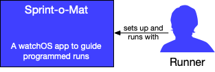
In a C4 System Boundary diagram, you start by drawing a blue box in the center. That’s your system. And you draw some blue stick figures with arrows pointing at that box. Those are your users.

An empty blue box next to blue human shape. An arrow is pointing from the human to the box.

Every system in the world pretty much looks the same if you stop there. Put some words on the parts to make it more specific.

A blue box next to blue human shape. An arrow is pointing from the human to the box. The blue box says "Sprint-o-Mat: a watchOS app to guide programmed runs" and under the human is a caption "Runner". An arrow points from the human to the box and says "sets up and runs with". This is the system in a context diagram.

But this diagram is called a Context diagram for a reason. The most important part is not the system box (the three other types of C4 diagrams will elaborate on it), but the all of the gray boxes and stick figures you put around it.

A blue box next to blue human shape. An arrow is pointing from the human to the box. The blue box says "Sprint-o-Mat: a watchOS app to guide programmed runs" and under the human is a caption "Runner". An arrow points from the human to the box and says "sets up and runs with". This is the system in a context diagram.

Under that are gray boxes that say HealthKit, RunGap and Running Social Networks. These are external context systems. There is a gray set of humans that say "other runners" The diagram show the relationship between them.

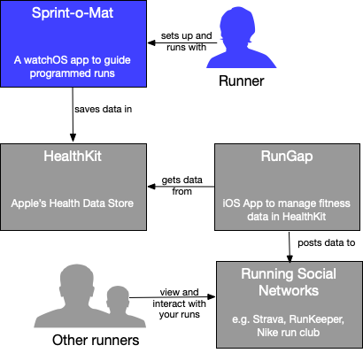
These are the external pieces that are not the system and who are not your users. They are out-of-scope, but do a lot of work in the diagram to help describe the system.